Functional Blocks and Ports
A functional block stands for one piece of equipment in a block diagram. Its ports are the equipment’s inputs and outputs, and the cables you draw between ports become your cable list. This page covers placing and naming blocks, working with ports, and arranging blocks on the page.
Anatomy of a functional block
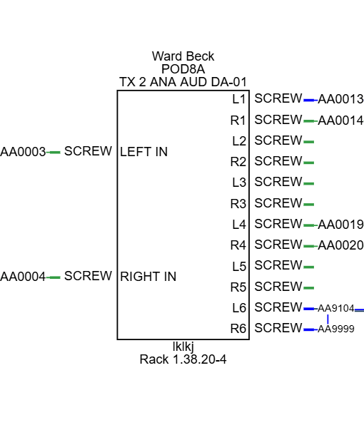
- Manufacturer, Model and SysName sit above the block, and Alias and Location below it. Drag a label to move it.
- Inputs are on the left side and outputs on the right. Each port has a port name, shown inside the block, and a connector, shown outside it next to a short colored stub. The stub’s color comes from the port’s signal type.
- Hover over a block to see its manufacturer, model and input and output counts.
Each kind of label has its own Text Kind (for example SysName or Left Ports), so you can style them separately on the Text tab. See Text.
Placing a block
- Open the drawing and expand Functional Block Prototypes in the library pane.
- Drag the prototype closest to what you need onto the canvas.
- Name the block and its ports (see below), and add or remove ports to match the equipment.
Prototypes are generic blocks with a few ports and placeholder names. New blocks use the stroke, fill and text style set under Settings (Active Stroke, Active Fill and Active Text Style); see Page Setup and Drawing Settings.
You can also place a block that already has the right ports from the Master Library, or reuse one you saved in a warehouse. See Master Library and Warehouses.
To resize a block, select it and drag a square handle. The ports spread out evenly along the block’s height. To rotate it, drag the round handle.
Naming blocks
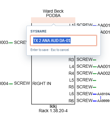
Click a label to edit it. A small card opens beside the label, naming the field you’re editing and showing the text at a readable size however far you’ve zoomed out. The label itself stays outlined on the drawing.
- Type the new text, then press Enter, press Tab or click elsewhere to save it.
- Press Esc to leave the label as it was.
- On a label that can hold several lines, press Shift+Enter to start a new line.
| Label | Use it for |
|---|---|
| Manufacturer | The equipment maker. |
| Model | The model name or number. |
| SysName | A unique name for this unit in the system, such as SPK-10 or SRVR-01. |
| Alias | A second, friendly name, such as what the operators call it. |
| Location | Where the unit lives. For rack panels mounted in a rack this is filled in for you; see Racks and Rack Panels. |
These names are carried into the cables connected to the block, and appear in the Equipment and Cables grids. See Project Data Grids.
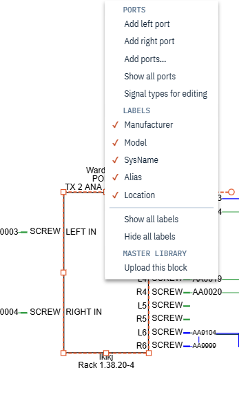
To hide or show labels, select one or more blocks and right-click one. Under Labels, a tick shows which labels the block you clicked is showing: Manufacturer, Model, SysName, Alias and Location. Click one to switch it. Every selected block follows the one you clicked, so a mixed selection ends up the same. Show all labels and Hide all labels switch every label at once.
How to name things
Choose names that will still be right after the next revision of the design. Equipment gets back-ordered, fails in the field and gets swapped for a different model, so avoid names that depend on details that can change.
- SysName is the unit’s identity. Build it from a short, abstract type prefix and a number:
SPK-10survives a change of speaker model,ATLAS12INCH70V-10does not. Keep every SysName unique in the project, so each unit can be found. - Alias holds the name people outside engineering use. Engineering may know twenty video servers as
SRVR-01toSRVR-20, while operations knowsSRVR-01as “Ingest Server”. Think of Alias as the friendly, operational, functional or logical name. It is also a handy place to note the source that feeds a downstream device, such as naming a distribution amplifier after the source it feeds. - Projects and drawings deserve names that stay true over time. “My New Project” won’t be new next year; “Summer 2026 Studio Modifications” still makes sense. Use readable drawing names rather than bare numbers.
Ports and connectors
Right-click the body of a block, or one of its port names, for the block menu. Its commands are grouped under headings, and settings you can switch on and off show a tick when they’re on.
- Under Ports:
- Add left port and Add right port add one port to that side, named
PORTn with connectorCONNn and the Default signal type. - Add ports… opens the Add Ports dialog; see Adding ports.
- Show all ports brings back hidden ports.
- Signal types for editing swaps connectors for signal types; see Port signal types.
- Add left port and Add right port add one port to that side, named
- Under Labels, the label ticks and Show all labels / Hide all labels; see Naming blocks.
- Under Master Library, Upload this block adds the block to the shared Master Library; see Master Library.
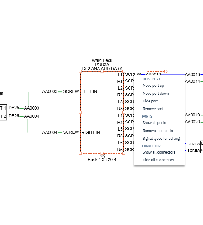
Right-click a connector label or port stub for the port menu:
- Under This port:
- Move port up and Move port down change the port’s order on its side.
- Hide port hides the port.
- Remove port deletes it.
- Under Ports:
- Show all ports shows hidden ports again.
- Remove side ports deletes every port on that side.
- Signal types for editing, as above.
- Under Connectors, Show all connectors and Hide all connectors show or hide the connector labels on the selected blocks.
Commands that change a block’s ports are hidden while the block’s position is locked.
Adding ports
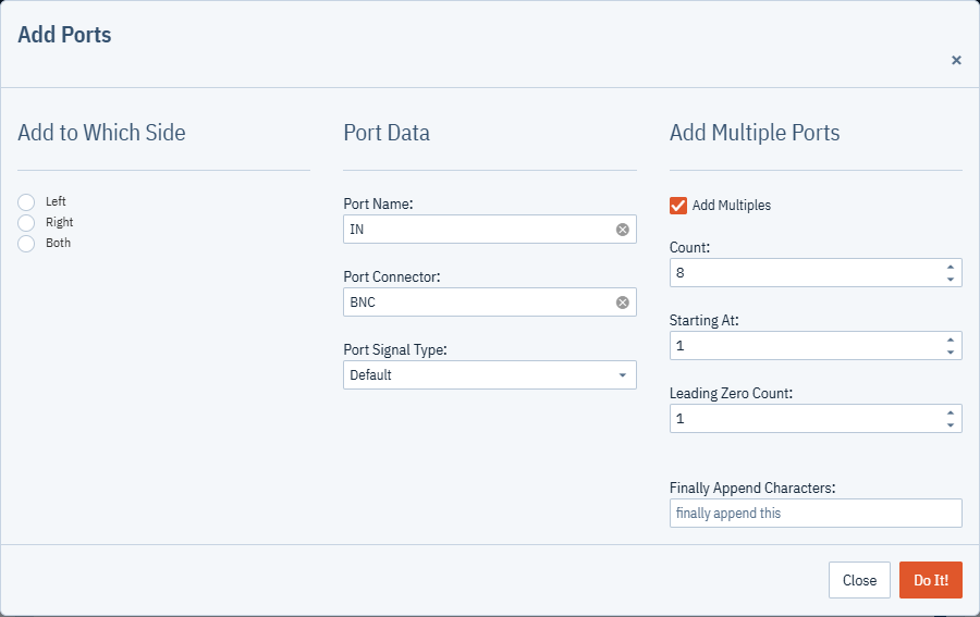
The Add Ports dialog adds one or many named ports at once. It works on every functional block in the selection.
- Select the block, or several blocks.
- Right-click the body of a block or one of its port names and choose Add Ports ….
- Under Add to Which Side, pick Left, Right or Both.
- Under Port Data, enter the Port Name, the Port Connector and the Port Signal Type. The signal type list comes from the project’s signal types.
- To add a numbered series of ports, check Add Multiples under Add Multiple Ports and fill in:
- Count: how many ports to add.
- Starting At: the first number in the series.
- Leading Zero Count: the minimum number of digits in the number. With 2, port 1 becomes
01; with 3 it becomes001. The most is 4. - Finally Append Characters: text added after the number.
- Click Do It!.
Without Add Multiples, the dialog adds one port with exactly the name you typed to each chosen side.
With Add Multiples, each port is named Port Name + number + appended characters, with nothing
added in between. For example, Port Name SDI IN , Count 4, Starting At 1,
Leading Zero Count 2 and Finally Append Characters A give SDI IN 01 A to SDI IN 04 A.
Include a trailing space in the port name if you want a space before the number. Every port in the series
gets the same connector and signal type.
New ports go below any existing ports on that side, and copy the text style of the first port already on that side. On an empty side they use Settings > Active Text Style.
Renaming ports and connectors
- Click the port name or connector label you want to change. The editing card opens beside it.
- Type the new name.
- Press Enter or click outside the card.
Cables already connected to the port pick up the new port name and connector.
Port signal types
Every port has a signal type, such as SDI, AES or Default, chosen from the project’s Signal Types. The signal type sets the color of the port stub and, when you connect a cable, the cable’s color, width and cable type. Signal types are normally hidden.
To change the signal type of ports:
- Show the signal types in place of the connector labels. Either:
- select the blocks, right-click one and tick Signal types for editing, or
- choose View > Show/Hide Signal Types for Editing to show them on every block in the drawing.
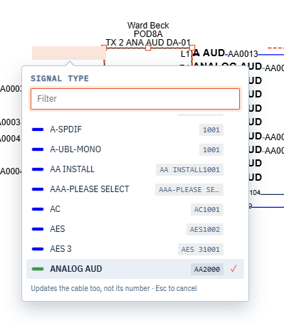
- Click a port’s signal type. A list of the project’s signal types opens beside it, sorted A to Z. Each row shows the type’s color, its cable type and the number the next cable of that type will get when cables are numbered.
- Type a few letters to narrow the list; it matches names, cable types and number prefixes. Click a type, or move to it with the arrow keys and press Enter. Press Esc, or click away, to leave the signal type as it was.
- Untick Signal types for editing, or repeat the View command, to put the connector labels back.
When you change the signal type of a port that has a cable, the port is recolored and the cable follows the new signal type, the same way it does when you apply the Signal Types grid:
- It takes the new color, width and line type, unless you set its color by hand.
- It takes the new cable manufacturer and cable type, unless you set them by hand.
- Its cable number stays as it is.
- The port at the other end of the cable takes the same signal type.
Undo reverses the whole change.
Lock Position and Count in BOM
The top of the General tab has two checkboxes that apply to the selected items.
- Lock Position keeps an item where it is. You can still select it and edit its text, but you can’t move, resize or rotate it, and the commands that add or remove ports are hidden. Locking a cable also locks the blocks at both of its ends; see Cable properties.
- Count in BOM decides whether the item is counted in the Bill of Materials. It is on for new functional blocks and racks, and off for rack panels. See Bill of Materials.
Grouping, aligning and stacking
Select two or more items, then use the Edit menu.
Grouping
- Make Group joins the selection into one group you can select and move as a unit. You can still move items inside it, and the group’s outline grows or shrinks to fit.
- Make Fixed Group joins the selection so the items keep their positions relative to each other and move only as a whole.
- Make Collapsible Group adds a button to the group that collapses it to a small box and expands it again. Cables to the group’s items reroute as it collapses.
- Ungroup separates a selected group back into its items.
Right-click a group to ungroup it or change it to another kind of group. Click the group’s title to rename it.
Make Fixed Group and Make Collapsible Group aren’t available on the Free plan. See Billing and Plans.
Alignment
Lefts, Rights, Tops and Bottoms line up the selected items with the edge of the item that is furthest in that direction. For example, Lefts moves every item so its left edge matches the left-most item.
Z-Order
Bring Forward and Send Backward move the selected items one step in front of or behind other items that overlap them. Click again to move another step.