Drawing Cables
A cable connects a port on one block to a port on another. Each cable carries data about both ends, its signal type, number, length and cable type, and that data feeds the Project Data Grids.
Drawing a cable
Cables are drawn with the Select Tool, not the Polyline Tool. A line drawn with the Polyline Tool is only a shape: it has no cable data, doesn’t stick to ports, and doesn’t appear in the Cables grid.
- In the Active Tool bar at the top of the right pane, make sure the Select Tool (the arrow) is active.
- Hover over the port you want to start from. The pointer changes to a hand.
- Drag to the port you want to connect to, and release.
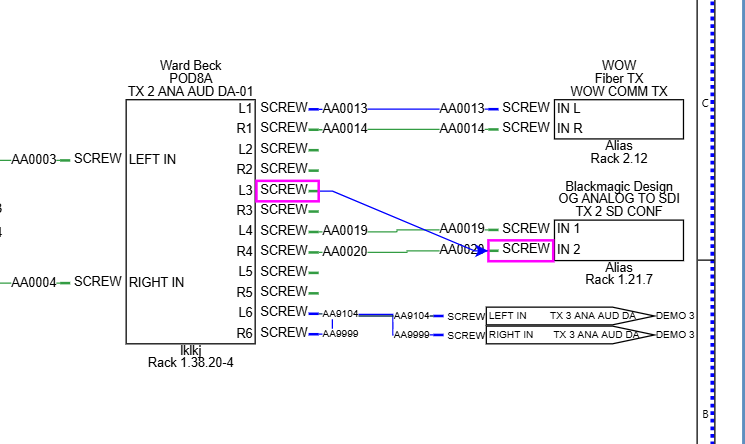
The new cable shows the placeholder text CableNo at both ends until you number it. See Cable numbers.
Draw each cable from the source port to the destination port. The port you start from is the From end:
- The cable takes the signal type of the From port.
- The To port’s signal type is changed to match.
- The cable’s color, width and cable type come from that signal type. See Signal Types.
To connect a port on one drawing to a port on another, cable each port to an off sheet pointer. See Off Sheet Pointers.
To delete a cable, select it and press Delete.
Moving and rerouting a cable
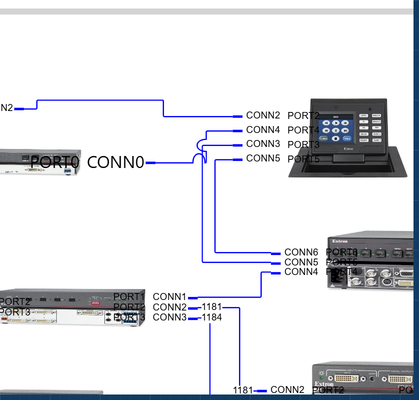
Cables route themselves around blocks. When you move a block, its cables follow and reroute.
To change a cable’s path by hand, click the cable to select it. Handles appear on the cable:
- End handles at each end: drag one onto a different port to reconnect that end.
- Segment handles on the straight runs: drag to slide a segment sideways. The cable stays at right angles.
- Midpoint handles: drag to add a new bend.
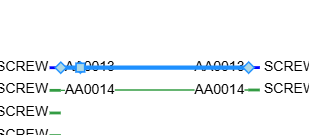
When you reconnect an end to a different port, the cable picks up that port’s name, connector and signal type.
To stop a cable from being moved or reshaped, turn on Lock Cable Position. See Cable properties.
Cable numbers
Simple Wires numbers cables from the project’s signal types. Each signal type has a Cable Number Prefix and a Next Cable Number. A cable’s number is the prefix followed by the next number. For example, with a prefix of AUD- and a next number of 1050, the next AUD cable is numbered AUD-1050, and the next number becomes 1051.
Leading zeros are kept: a next number of 0001 gives 0001, then 0002.
The next numbers are stored with the project, so numbering in one drawing carries on where the last drawing left off. To set them, see Signal Types.
The numbering commands work on the drawing that is open.
Number all cables
Choose Cables > Number All, then click Yes, Number ALL Cables.
Every cable in the drawing gets a new number, including cables you have already numbered or edited by hand.
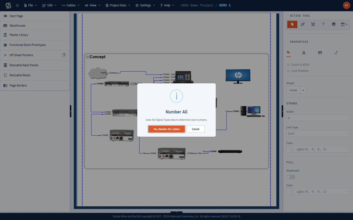
If a cable’s signal type isn’t in the project’s signal types, Simple Wires adds it before numbering, using the signal type name as the prefix and 1001 as the next number.
Number remaining cables
Choose Cables > Number Remaining, then click Yes, Number Remaining.
Only cables that still show the placeholder CableNo are numbered. Cables that already have a number, including numbers you typed yourself, are left alone. Use this after adding cables to a drawing you have already numbered.
Reset all cable numbers
Choose Cables > Reset All. Every cable in the drawing goes back to CableNo. There is no confirmation, but you can undo it with Edit > Undo.
Reset All doesn’t change the signal types’ next numbers. To start numbering again from a particular number, reset the next numbers in the Signal Types grid first.
Editing a cable number
- Click the cable number at either end of the cable. The text opens for editing.
- Type the new number.
- Click outside the text.
Both ends of the cable show the new number.
Simple Wires doesn’t check for duplicate cable numbers.
Numbering cables that cross drawings
A cable that runs through off sheet pointers appears in both drawings, and its number is copied from one to the other. Number the drawing that holds the source equipment, then use Number Remaining in the other drawing.
Cable jumps, corners and routing
The Cable Behavior settings control how all cables in the drawing look where they cross and turn. Open the Settings menu and find the Cable Behavior column. The settings are saved with the drawing.
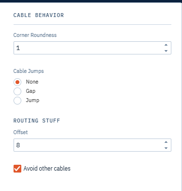
| Setting | What it does |
|---|---|
| Corner Roundness | Rounds the corners where a cable turns. 0 gives square corners. |
| Cable Jumps | What a cable shows where it crosses another cable: None (the lines cross), Gap (a break in the line) or Jump (a small hop over the other cable). |
| Offset | Under Routing Stuff. The spacing between parallel cables leaving neighboring ports on the same side of a block. Larger values spread the cables further apart. |
| Avoid other cables | Under Routing Stuff. Keeps cables from running on top of each other. |
The other columns of the Settings menu are covered in Page Setup and Drawing Settings.
Cable color and signal types
By default a cable is drawn with the stroke color, width and line type of its signal type. When you change a signal type in Project Data > Signal Types, every cable of that type in the project changes to match. See Signal Types.
To give one cable its own look, select it, open the Cable tab and turn off By Signal Type under Stroke. Then set Width, Line Type and Color yourself.
To change the Font, Size and Foreground color of the cable numbers, select the cables and use the Text tab in the right pane.
Cable properties
The Cable tab in the right pane shows the properties of the selected cable. Select a cable, then click the Cable tab (the cable icon). If you select several cables, a change applies to all of them. A setting that differs between the selected cables shows as blank.
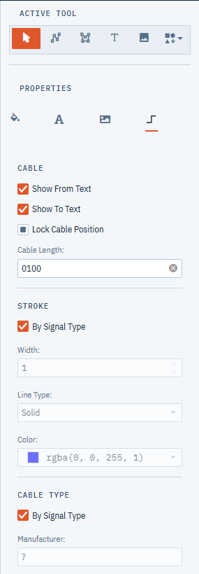
- Show From Text
- Shows or hides the cable number at the From (source) end.
- Show To Text
- Shows or hides the cable number at the To (destination) end.
- Lock Cable Position
- Stops the cable from being reshaped or reconnected. Locking a cable also locks the blocks at both ends so they can’t be moved. Turning the lock off again unlocks only the cable; unlock the blocks separately.
- Cable Length
- The cable’s length. It appears in the Length column of the Cables grid. In the Bill of Materials, lengths are added up for each cable type.
- Stroke
- By Signal Type: when on (the default), the cable’s width, line type and color come from its signal type, and the fields below are unavailable. Turn it off to set them for this cable.
- Width: the line width, 0 to 20.
- Line Type: Solid, Dot, Dash, Long Dash, Dash Dot, Dash Dot Dot, Dash Dot Dot Dot Dash or Dot Dash Dot.
- Color: the line color.
- Cable Type
- By Signal Type: when on (the default), the manufacturer and type come from the signal type’s Cable Manufacturer and Cable Type. Turn it off to enter them for this cable.
- Manufacturer: the cable manufacturer.
- Type or P/N: the cable type or part number.
The cable type is what the Bill of Materials counts under Cable Types. See Project Data Grids.
For a cable connected to an off sheet pointer, changes to these properties are copied to the matching cable in the other drawing.