Page Setup and Drawing Settings
Each drawing has its own page size, margins and unit of measure, plus a set of active styles that new items pick up. You set these from the Settings menu, and you control the grid, snapping, guidelines and zoom from the View menu. Simple Wires saves all of these settings with the drawing, so every drawing in a project can use a different sheet size.
The Settings menu
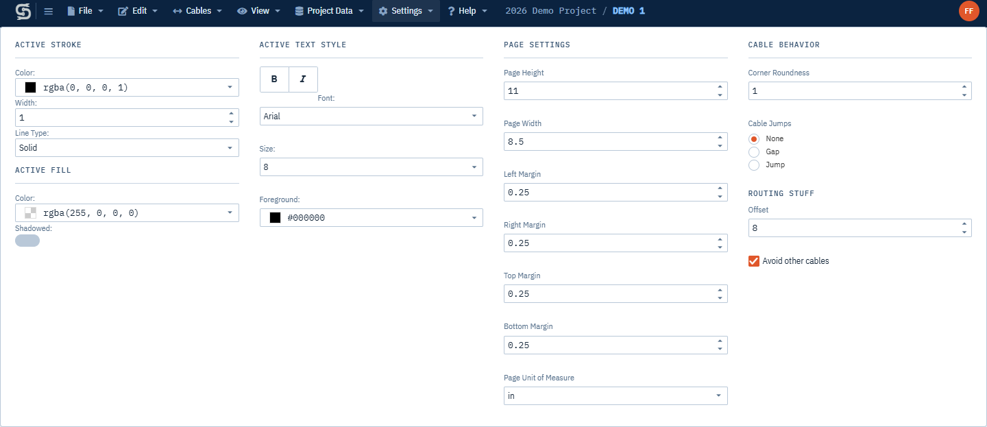
Open a drawing and click Settings in the menu bar. The menu has four columns:
- Active Stroke and Active Fill
- Active Text Style
- Page Settings
- Cable Behavior (corner roundness, cable jumps and routing; see Drawing Cables)
Changes take effect as soon as you make them; there is no OK button.
The Settings menu only appears while a drawing is open, and it is hidden if you have view-only access to the project.
Page size and margins
The Page Settings column sets the sheet the drawing is laid out on.
| Field | What it does |
|---|---|
| Page Height | Height of the sheet. |
| Page Width | Width of the sheet. Make it larger than the height for a landscape sheet. |
| Left Margin, Right Margin, Top Margin, Bottom Margin | The printable area inside the sheet edge. |
| Page Unit of Measure | in, mm or cm. All six fields above use this unit. |
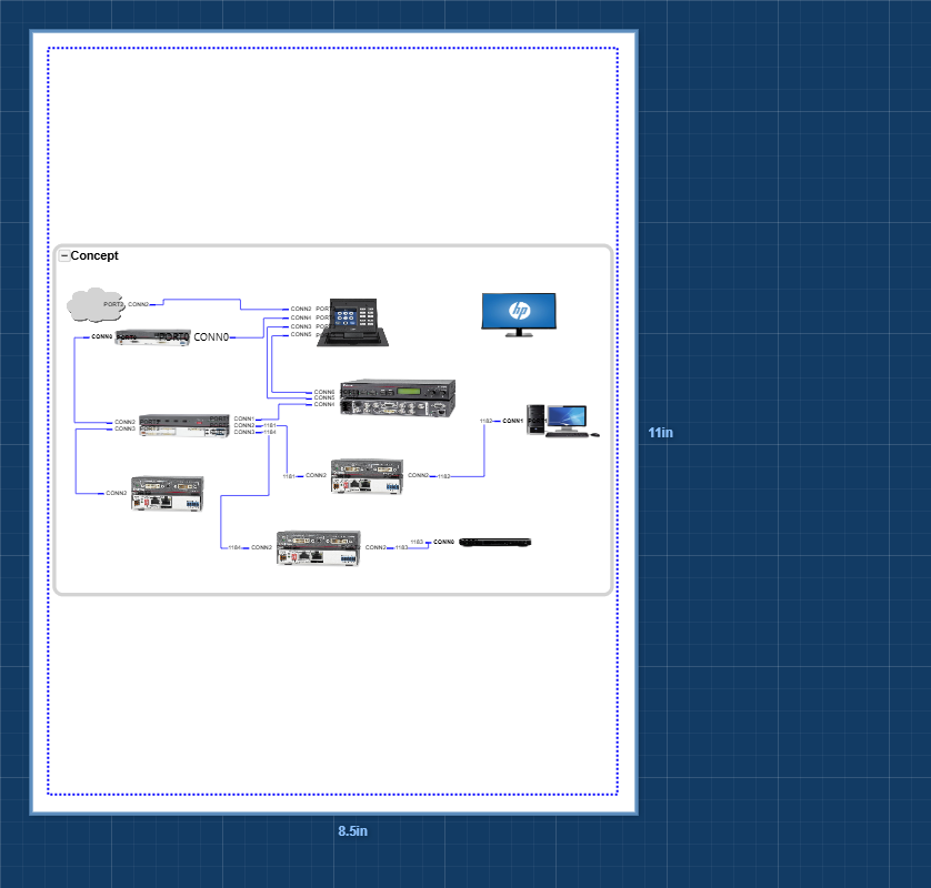
The editor draws the sheet as a white page with its height and width written beside it, and shows the margins as a blue dashed rectangle. Keep your drawing inside the margins: PDF and DWG exports include only the area inside the margins, and printing includes only the sheet. See Printing and Exporting.
To set up a sheet:
- Open the drawing.
- Click Settings.
- Choose the Page Unit of Measure first.
- Enter the Page Height, Page Width and the four margins.
Changing Page Unit of Measure doesn’t convert the numbers. An 11 by 8.5 page switched from
intommbecomes an 11 mm by 8.5 mm page. Pick the unit first, then type the sizes in that unit.
Defaults for new drawings
A new drawing starts at 11 in wide by 8.5 in high with 0.5 in margins, unless you’ve changed your defaults. On a paid plan you can change the page size, margins, unit, active stroke and active fill used for new drawings with the Config button on the Projects Dashboard. Changing the defaults doesn’t alter drawings you’ve already created.
Active stroke, fill and text style
The active settings are the styles Simple Wires gives to items you add from now on. They don’t change items that are already in the drawing. To restyle an existing item, select it and use the property window instead (see Shapes, Text and Images).
Active settings apply to:
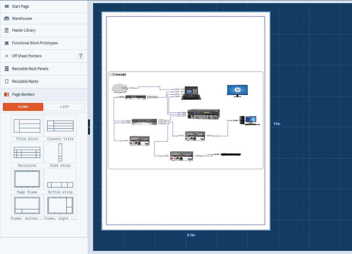
- Items you drag from the Functional Block Prototypes, Resizable Rack Panels, Resizable Racks and Page Borders lists in the left pane. The previews in those lists update as you change the settings.
- Shapes, polylines, polygons, text boxes and images you draw with the drawing tools.
- Equipment you add from the Master Library, when the library item doesn’t carry its own stroke color.
| Setting | Options |
|---|---|
| Active Stroke > Color | Line color, including transparency. |
| Active Stroke > Width | Line width, from 0.1 to 20. |
| Active Stroke > Line Type | Solid, Dot, Dash, Long Dash, Dash Dot, Dash Dot Dot, Dash Dot Dot Dot Dash, Dot Dash Dot. |
| Active Fill > Color | Fill color, including transparency. |
| Active Fill > Shadowed | Adds a drop shadow. |
| Active Text Style | Bold, italic, Font (Arial, Calibri or Verdana), Size (6 to 72) and Foreground color. |
The active text style is also used for the labels on new cables and for the port labels on a functional block side that has no ports yet.
Page borders
Page borders are the title blocks and frames you place on the sheet to describe the drawing.
- In the left pane, click Page Borders to expand the list. There are title blocks, a revision table, page frames and title strips; see Page borders for what each one holds.
- Drag a border onto the page. The page frames and strips size themselves to the drawing’s margins.
- Resize the others to fit inside your margins.
- Select a text label to edit it, and add your logo as an image.
A page border’s outline and fill come from Active Stroke and Active Fill at the time you drag it in, and its text comes from Active Text Style. A page border isn’t tied to the page size, so if you change the page size, resize the border to match.
Grid, snapping and guidelines
The drawing’s View menu has switches that change how you place items. Each switch is saved with the drawing.
| Switch | What it does |
|---|---|
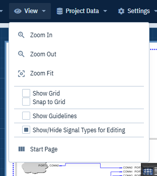
| Show Grid | Shows a light gray grid over the page. The grid spacing is a tenth of the page unit: 0.1 in, 1 mm on a cm page, or 0.1 mm on a mm page. |
| Snap to Grid | Moving and resizing items snaps them to the grid, whether or not the grid is showing. |
| Show Guidelines | While you drag an item, blue and green guidelines show when its edges or center line up with nearby items, and the item snaps into line when you drop it. Hold Shift as you drop to place it without snapping. |
| Show/Hide Signal Types for Editing | On functional blocks, shows each port’s signal type in place of its connector label, so you can check and edit signal types. Turn it off to show connectors again. See Signal Types. |
Rack panels ignore grid snapping while you drag them, so they can seat in the rack. See Racks and Rack Panels.
Zoom
Use the View menu to change the magnification:
- Zoom In and Zoom Out step the magnification up or down.
- Zoom Fit fits everything in the drawing into the window.
You can also zoom with the mouse wheel over the drawing, and with the keys listed in Keyboard Shortcuts. Zoom only changes your view; it doesn’t affect printing or exports.